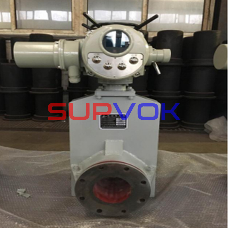
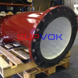
Hydrocyclone valve
Advanced ceramic valve
The applications of metal valves has a history of more than one hundred years. Although the structure and materials have also been improved during the period, they are limited by the conditions of the metal materials themselves. It is increasingly unable to meet the needs of severe working conditions such as high wear and strong corrosion under special environment. The frequent leakage caused by short service life and poor sealing affects the stability of the system operation to a certain extent.
With the rapid development of chemical industry, a variety of special projects such as strong corrosion, high temperature and pressure, and high toxicity are increasing, which puts forward higher requirements for the valve, the most commonly used component in chemical pipeline, such as superior strength, hardness, insulation, heat conduction, high temperature resistance, oxidation resistance, abrasion resistance, wear resistance, high temperature strength, etc. Under very severe environment or engineering application conditions, new ceramic valves with high stability and excellent mechanical properties emerge as the times require.
Advanced ceramic valves can be customized according to the actual working conditions of customers.
Through adopting high-precision processing technology and taking advantage of structural ceramics’ natural advantages, it can easily obtain good sealing and light torque, which can effectively avoid the phenomenon of sealing surface pulling and ball core locking. The tenon type sealing structure is adopted between the valve seat and the valve body lining. That structure can ensure the good sealing performance of valve under high working pressure.
The stuffing box adopts a high neck structure, which provides a double guarantee for the valve stem seal. Graphite packing is used to ensure the tightness of the valve at high temperature and high pressure. It adopts the design of anti ejection structure to prevent the valve stem from ejecting from the valve under high working pressure, thus ensuring safety.
Advantages and characteristics of new ceramic valves
(1)Long service life
Compared with valves made of other materials, ceramic valves have a long effective service life under the working environment of high temperature and strong pressure. This not only ensures the normal operation of the chemical transportation industry to a certain extent, but also reduces the cost of chemical production and improves the working efficiency of valves.
(2)Wide application scope
Ceramic valves are applicable to a wide range, such as power production, chemical industry, metallurgy and mining. In addition, ceramic valves are also applicable to industrial fields such as sewage treatment.
(3)Mature production technique
With the continuous innovation and development of science and technology, the preparation process and flow of ceramics become more mature and perfect. For example, the important technological links such as the product proportioning ratio of ceramics and the processing and molding of ceramics are more mature through the application of new technologies.
(4)Wide source of raw materials
The raw materials for preparing ceramic valves come from a wide range of sources. The raw materials containing aluminum and silicon can be used to prepare ceramics after processing.
(5) Superior performance
Ceramic valves are superior to other types of valves in terms of high temperature resistance, wear resistance and corrosion resistance. In addition, it also has good airtightness and thermal conductivity.
(6)Low production cost
Due to the common selection of raw materials for producing ceramics, it saves a lot of rare metal resources. Moreover, the application of ceramic valves can effectively reduce the labor intensity of workers, and the system operation is relatively stable. The cost of the whole system maintenance and valve replacement is relatively low, which effectively saves the operation cost.
The hardness of ceramic valve sealing surface and fluid contact part is very high (Rockwell HRA ≥ 88 or above), which is equivalent to Rockwell HRC ≥ 70 or above. The ceramic valve has stable performance, and the ceramic parts have superior self-lubricating property. Therefore, the torque of ceramic valve is very small, which is convenient for remote control.
Common components and valve types of ceramic valves
There are two types of ceramic valves in the specific composition.
The first method is to set a layer of ceramic protective film on the metal surface by ceramic inlay or bonding, and use metal as the supporting framework system of ceramics.
Advantages: The framework of metal part has strong hardness and ductility, which can not only effectively overcome the characteristics of high brittleness but low strength of ceramics, but also play the role of ceramic protection.
The second is based on solid ceramic structure. Through multi-layer process treatment, such as static pressure forming, hot reduction sintering and other processes, it can avoid the technical problems brought by the limitations of ceramic valves to the greatest extent.
In application process of ceramics, the connection mode of valves needs to be selected according to the properties of ceramics. For example, in the design and manufacture of ceramic ball valves and ceramic butterfly valves, the butterfly valves and ball valves have special structures that make them unsuitable for inlaying or bonding. The main chemical composition of ball valve and butterfly valve ceramics is ZrO2. There are also some differences between the ceramic firing and treatment process and Al2O3 type ceramics.
Application of ceramic valves in engineering field
At present, ceramic valves have been widely used in flue gas desulfurization (FGD) devices, fly ash, slag removal and combustion (coal injection) systems of power plants, sintering machine desulfurization (EPC) projects of iron and steel plants, flue gas purification of waste incineration, chlor alkali industry, wastewater and solid waste treatment industries and other industries.
Facing the harsh working environment, ceramic valves have unique advantages and good performance compared with valves with other material properties in the application of chemical pipelines. For example:
(1) Effectively avoid the abrasion and corrosion of limestone, gypsum slurry, chloride ion and other impurities;
(2) Effectively prevent corrosive industrial dust and wear of steel powder and iron powder;
(3) Effectively deal with solid waste;
(4) Meet the production demand of chlor alkali manufacturing industry.
With the increasingly high social requirements for environmental protection, economy performance, product performance, and the continuous innovation of technology, it makes ceramic valves more and more widely used, mechanical properties more and more stable, and economic value more and more high. Under the working conditions of strong corrosion and severe erosion, its service life is 2~5 times that of rare metal valves such as titanium, nickel, and so on.
Cyclone valve
Before using the cyclone, check whether the cyclone and pipeline are in normal condition. The number of hydrocyclones used shall be determined according to the amount of ore coming. Please open the valve using the cyclone and close the standby cyclone valve.
1.Before commissioning, ensure that all connection points of cyclone unit are fastened. Remove all kinds of residues in the pipeline and unit box to avoid leakage and blockage after start-up. Please ensure that the cyclone valve put into operation is fully opened.
2.The valve can be fully opened (such as running cyclone) or completely closed (such as standby cyclone). However, the valve is never allowed to be in the semi open state, that is, it is never allowed to control the flow with the valve.
3.If possible, please test drive with clean water first. The feed of cyclone can be provided by pumping or high level tank. If the pump and cyclone throughput match, the pressure gauge shows a constant reading. Please ensure that the pressure gauge reading does not fluctuate. If there is obvious fluctuation, check the cause. The equipment is required to work under the pressure not higher than 0.3MPa.
4.When the equipment operates stably under normal pressure, check the leakage of connection points and take remedial measures if necessary.
5.Please check the blockage caused by the residue entering the cyclone. If the feed inlet of the cyclone is blocked, the overflow and grit flow will be reduced. If the sand setting port of the hydrocyclone is blocked, the sand setting flow will be reduced or even cut off, and sometimes severe vibration will occur. In case of blockage, the feeding valve of cyclone shall be closed in time to remove the blockage. In order to prevent blockage, facilities (such as vibrating screen) to prevent coarse materials and sundries can be added in the feed tank of the hydrocyclone group. Meanwhile, the feed tank shall be emptied in time during shutdown to avoid blockage accidents due to sedimentation and high concentration during restart.
6.When the equipment is proved to operate well by clean water test, the slurry can be input for operation. During the normal operation of the equipment, the stability of the pressure gauge, the overflow and grit flow, and the discharge state shall be checked frequently, and the overflow and grit concentration and fineness shall be checked regularly.
Ash and slag removal valve
The slag discharge check valve is mainly used as a check device to transport the mixture medium of slurry, mortar, sewage and ash in mining, metallurgy, power, chemical industry, sewage discharge and other industries with a working temperature of ≤ 120C and a pressure of no more than 4.0MPa.
Wedge gate valve
Wear resistant adjustable pulverized coal valve
Gate valve stop valve
Slag discharge check valve
Wear resistant expansion device
Cast stone wear-resistant ball three-way directional valve
Manual and electric wear and corrosion resistant ball valve
Plate gate valve
Wear resistant slag discharge gate valve
Electric wear-resistant pulverized coal gate valve
Wear resistant and anti scaling gate valve
Throttle valve
Combined stop throttle valve
Wear resistant throttle valve
Dry ash gate valve
|
Products |
Material |
Industrial applications |
product types |
Application system example |
|
Advanced ceramic valve |
Advanced ceramics, enamel, ordinary ceramic valves, fluorine lined valves, metal valves, etc |
Widely used in coal, mining, petroleum, chemical, thermal power, pharmaceutical, steel, smelting, machinery, water conservancy, ports, docks and other industries with severe wear and tear |
Ceramic ball valve series Ceramic butterfly valve series Ceramic discharge valve Ceramic feed valve Ceramic check valve Pneumatic dome valve Ceramic slag discharge valve Ceramic gate valve Pressure reducing valve series Fluorine lined valve Enamel valve, etc |
Chemical system Limestone conveying system Dust free pebble hopper discharge system Mechanical hydraulic slag removal system Polycrystalline silicon special valve Negative pressure pneumatic ash removal system Fly ash sorting system |
Ball value sizes
|
DN |
L |
D |
D1 |
D2 |
n-Φd |
b |
f |
H |
|
|
mm |
in |
||||||||
|
15 |
1/2″ |
130 |
95 |
65 |
45 |
4-Φ14 |
14 |
2 |
86 |
|
20 |
3/4″ |
130 |
105 |
75 |
55 |
4-Φ14 |
14 |
2 |
95 |
|
25 |
1″ |
140 |
115 |
85 |
65 |
4-Φ14 |
14 |
2 |
108 |
|
32 |
1 1/4″ |
165 |
135 |
100 |
78 |
4-Φ18 |
16 |
2 |
115 |
|
40 |
1 1/2″ |
165 |
145 |
110 |
85 |
4-Φ18 |
16 |
3 |
115 |
|
50 |
2″ |
203 |
160 |
125 |
100 |
4-Φ18 |
16 |
3 |
115 |
|
65 |
2 1/2″ |
222 |
180 |
145 |
120 |
4-Φ18 |
16 |
3 |
115 |
|
80 |
3″ |
241 |
195 |
160 |
135 |
8-Φ18 |
20 |
3 |
145 |
|
100 |
4″ |
305 |
215 |
180 |
155 |
8-Φ18 |
20 |
3 |
188 |
|
125 |
5″ |
356 |
245 |
210 |
185 |
8-Φ18 |
22 |
3 |
210 |
|
150 |
6″ |
394 |
280 |
240 |
210 |
8-Φ23 |
24 |
3 |
260 |
|
200 |
8″ |
457 |
335 |
295 |
265 |
12-Φ23 |
26 |
3 |
320 |
|
250 |
10″ |
533 |
405 |
350 |
320 |
12-Φ25 |
30 |
3 |
365 |


